Noise
Some components in Zero produce noise, such as resistors (Johnson noise) and op-amps (voltage and current noise). Other components such as capacitors and inductors do not produce noise by default, although noise can be added by the user.
Johnson noise
Johnson noise is a type of voltage noise in resistors that arises from thermal agitation of charge carriers. This is a function of temperature but has no dependence on applied voltage or current.
The default temperature assumed in Zero calculations is set in the configuration.
Op-amp noise
Op-amps produce voltage noise across their input and output nodes, and current noise is present at their input nodes.
Op-amp voltage noise
Op-amps produce voltage noise across their input and output nodes. The noise is a function of frequency, usually with a flat component at all frequencies and a component rising towards low frequencies. The cross-over between these two noise components is typically around 1 to 100 Hz, though this varies depending on the type of op-amp. BJT-based op-amps typically have the lowest voltage noise.
Op-amp current noise
Current noise is present at op-amps’ inputs. The noise is a function of frequency, usually with a flat component at all frequencies and a component rising towards low frequencies. The cross-over between these two noise components is typically around 100 Hz to 1 kHz, though this varies depending on the type of op-amp. FET-based op-amps typically have the lowest current noise.
Current noise is converted to voltage noise by resistors connected to the op-amp inputs. That means that in a standard op-amp circuit with a feedback resistor, the current noise scales with the feedback resistance.
In Zero, current noise is considered identical for both input nodes. This is usually a valid assumption for voltage-feedback op-amps, which are the type that Zero models.
Defining new noise sources
New noise sources can be defined in Zero and added to components. The noise will then appear in noise analyses.
Noise sources can be created by subclassing one of the available noise types: VoltageNoise
or CurrentNoise. The implementation must define a label property and set a method to
call when computing the noise. This method will receive the current frequency vector and it must
return the corresponding noise.
Here is an example of defining a resistor current noise source and using it in a circuit:
import numpy as np
from zero import Circuit
from zero.analysis import AcNoiseAnalysis
from zero.noise import VoltageNoise
# Create a new noise type.
class ResistorCurrentNoise(VoltageNoise):
"""Resistor current noise source.
This models resistor current noise. See e.g. https://dcc.ligo.org/LIGO-T0900200/public
for more details. This noise depends on resistor composition and on its current. Be
careful when using this noise - it generally does not transfer to different circuits
with identical resistors as it depends on the voltage drop across the resistor.
Parameters
----------
vnoise : :class:`float`
The voltage noise at the specified frequency (V/sqrt(Hz)).
frequency : :class:`float`
The frequency at which the specified voltage noise is defined (Hz).
exponent : :class:`float`
The frequency exponent to use for calculating the frequency response.
"""
def __init__(self, vnoise, frequency=1.0, exponent=0.5, **kwargs):
super().__init__(**kwargs)
self.vnoise = vnoise
self.frequency = frequency
self.exponent = exponent
def noise_voltage(self, frequencies, **kwargs):
return self.vnoise * self.frequency / frequencies ** self.exponent
@property
def label(self):
return f"RE({self.component.name})"
# 1000 frequencies between 0.1 Hz to 10 kHz
frequencies = np.logspace(-1, 4, 1000)
# Create circuit object.
circuit = Circuit()
# Add components.
circuit.add_capacitor(value="10u", node1="gnd", node2="n1")
circuit.add_resistor(value="430", node1="n1", node2="nm", name="r1")
circuit.add_resistor(value="43k", node1="nm", node2="nout")
circuit.add_capacitor(value="47p", node1="nm", node2="nout")
circuit.add_library_opamp(model="LT1124", node1="gnd", node2="nm", node3="nout")
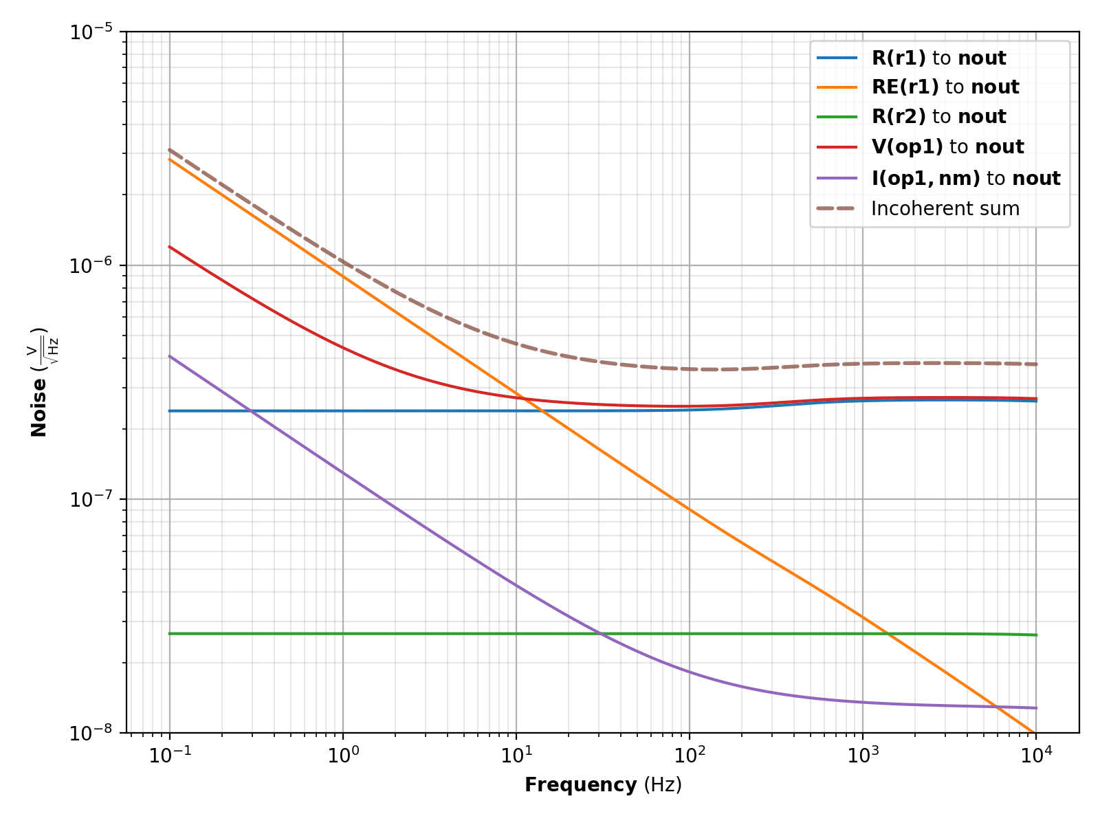
# Add resistor current noise to r1 with 10 nV/sqrt(Hz) at 1 Hz, with 1/f^2 drop-off.
r1 = circuit["r1"]
r1.add_noise(ResistorCurrentNoise(vnoise=1e-8, frequency=1.0, exponent=0.5))
# Solve circuit.
analysis = AcNoiseAnalysis(circuit=circuit)
solution = analysis.calculate(frequencies=frequencies, input_type="voltage", node="n1",
sink="nout", incoherent_sum=True)
# Plot.
solution.plot_noise(sink="nout")
solution.show()
(Source code, png, pdf)